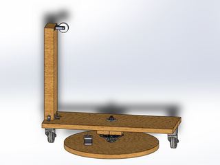
The Base and Aiming Mechanism
Our goal when designing a base for our tracking and launch system was simple: design a cost-effective base without sacrificing efficiency and integrity. The initial concept was to incorporate a lazy mechanism using a bike gear. For the aiming of the cannon, we will fixed the angle of launch (pitch) to 50° or higher to allow for easier catching. The yaw will be controlled with the use of a makeshift turntable and an attached stepper motor. We decided to use a stepper motor to rotate the entire base by connecting the motor to the cog of the bike wheel via a shortened bike chain. We added caster wheel for stability, and decided to let the caster wheels be free rolling to minimize friction thereby maximizing efficiency. We have attached a 50cm. long 2x4 to the back of the base for two reasons. The first reason is to house the tracking device, and insure the devices line of sight will never be obstructed by the launching system. The second reason was to add a pivot point for a cord to wrap around, so we can adjust the pitch angle of the front of the launching system.
The cocking and release mechanism
The main purpose of the cocking mechanism is to prime the spring by pulling the carriage away from the exit plate (with the spring between the two). This will require linear actuators to draw the launching carriage away from the exit plate as well as a release mechanism.
There are various linear actuation methods, which includes ball screw, lead screw, timing belt, rack and pinion and linear motors. To prime the spring, linear motors would be most ideal as they provide high speed, acceleration, and precision with minimal backlash following error and settling times. However they are the most costly. Timer belts might not be able to hold on to the carriage to prime the spring.
Comparing the ball screw, lead screw and rack and pinion, a survey on McMaster-Carr website shows that lead screws are most cost effective as they are fairly precise despite their slower response time. Although this will increase loading time, it is still within range of about 30 seconds. With the lead screw there is an inherent self-locking mechanism that will prevent the cocking mechanism from pre-launching (back driving due to the spring) upon loss of power. In order to choose the screw we need to consider the lead of the screw. A higher lead will result in faster cocking but it will be harder to vary the power to launch the can (as a one revolution of the screw will result in a larger increase in power). To determine the balance of speed and control we need to consider the desired reloading time. A 30 sec maximum reload time would mean that the cocking plate have to move 12 inches in 30 sec. This means a lead of 0.1 inches/thread, would result in a required revolution of 4 revolution per sec or 240 rpm. Torque required to cock the system can be calculated as follows:
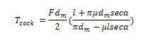
Where F is the max force from the spring, is the diameter of the screw, is the frictional coeffiecient and is the thread angle. The force needed to fully extend the spring can be calculated as where is 12”. With the max torque required we can determine which stepper motor to get.
Release Mechanism
The release mechanism will be attached to the cocking plate and would require enough force to hold on to the launching carriage when cocking. It has to be able to release the launching carriage instantly to ensure that the power from the spring is fully transmitted to the can. Hence, an electromagnet, with the magnet on the cocking mechanism and the mating plate on the launching plate. This would be more ideal over a mechanical solution. The electromagnet would require a holding strength of at least 30 pounds to cock the launching plate to ensure that it does not release due to insufficient force.
Tracking Mechanism
We plan to mount our Kinect on top of the launcher, so that they all share a common reference frame. Thus, users a certain distance from the Kinect, as well as at a certain angle from the center of the frame, will be at the same distance and angle from the launcher, making coordination between the tracking and launching easier and more intuitive. The Kinect will actively track users based on the built-in skeletal tracking system. It tracks the position of 20 major joints of a user and assigns a player index to each person tracked. We can use this player index to choose which target the Kinect selects as the active user. The Kinect also gives us the distance of the user from itself, thus giving us the distance the can needs to be launched. Our plan is to have our Kinect track users, and rotate to center the active user in the video frame. The launcher will also rotate along with the Kinect and once it acquires the launch distance from the Kinect, will be ready to launch. However, the trigger condition for the launch is twofold to ensure user safety and minimize the chance of accidental and unintended launches. To do this, the Kinect will launch only when it hears a required phrase, and then “sees” a clap. The required phrase will be programmed into the Kinect and must be enunciated clearly. The Kinect will recognize the clap when the active user’s right and left hands have the same position (which is being tracked by the skeletal tracking system). Both conditions will be necessary in a short time frame for the system to launch a can.
